
Fluid mechanics Products
Bernoulli
Code : (MF-31)
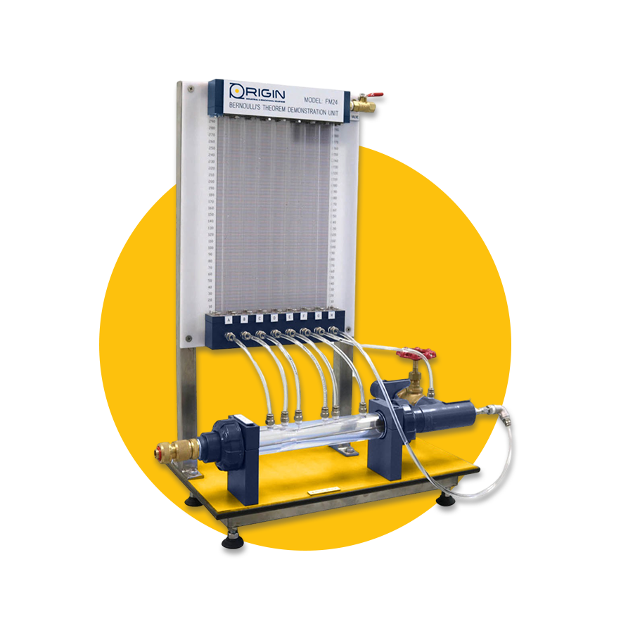
The demonstration unit of Bernoulli's principle typically showcases Bernoulli's theory, which explains the correlation between fluid flow velocity and pressure. Measure the pressure in a venturi nozzle to achieve this.The experimental unit includes a pipe section with a transparent Venturi nozzle and a movable Pitot tube for measuring the total pressure. The Pitot tube is located within the Venturi nozzle, where it is displaced axially. The position of the Pitot tube can be observed through the Venturi nozzle’s transparent front panel.
The Venturi nozzle is equipped with pressure measuring points to determine the static pressures. The pressures are displayed on the six tube manometers. The total pressure is measured by the Pitot tube and displayed on another single tube manometer.
The demonstration unit of Bernoulli's principle typically showcases Bernoulli's theory, which explains the correlation between fluid flow velocity and pressure. Measure the pressure in a venturi nozzle to achieve this.
• Venturi Nozzle Velocity Profile
• Venturi Nozzle Pressure Distribution
• Calculating Flow Rate Factor
Vortex
Code : (MF-32)
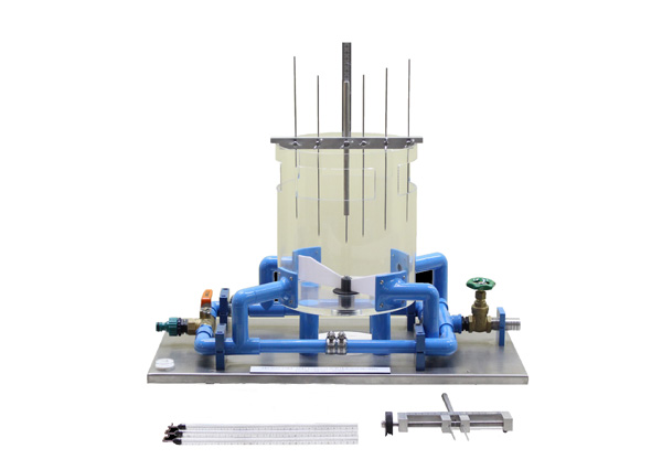
The vortex formation apparatus is a compact kit designed to be connected to the hydraulic main unit, offering a valuable learning experience for trainees.
The kit demonstrates how to create and study free and forced vortices, and includes various inserts for water drainage purposes.
• Visualizing free and forced vortices in action.
• Creating free and forced vortices experimentally.
• Depicting surface profiles in diagrams.
• Studying how the direction of the jet inlet affects the vortices.
Jet forces
Code : (MF-33)
The educational unit focuses on measuring jet forces to study the impact of a steady flow of water on a solid surface and observe the resulting deflection. This unit allows for experiments to be conducted to analyze the reaction force generated by deflectors when they are hit by a jet of water. Understanding these reaction forces is crucial in fluid mechanics study.
• Investigating the effects of jet forces through demonstrations
• Analyzing the influence of jet forces at different angles (flat, oblique, semicircular, conical)
• Exploring the connection between fluid flow rate and velocity
• Establishing the energy equation from the nozzle exit to the deflector's surface
Hydraulic bench
Code : (MF-34)
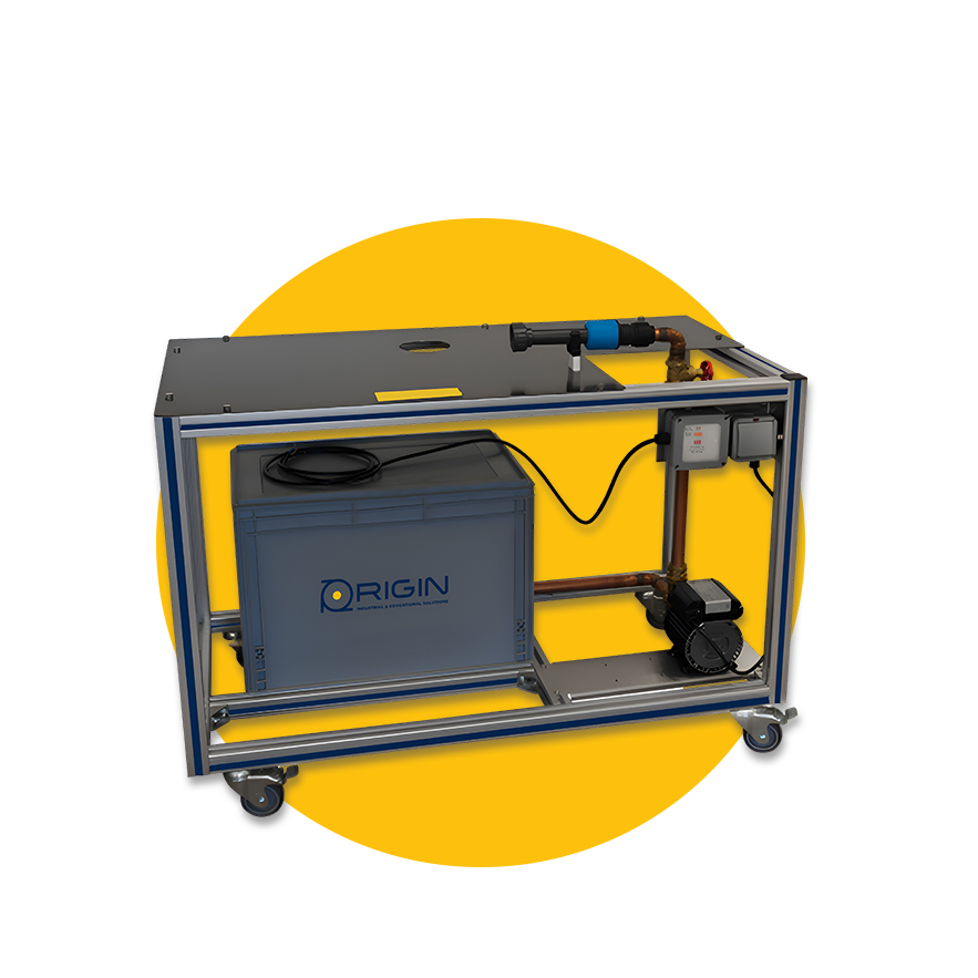
The hydraulics bench (MF-34) is mounted on lockable castor wheels and is constructed around a sturdy framework onto which all elements of the hydraulics bench are mounted. The main water storage tank from which the electrically operated external pump takes its water is situated on the framework. An on/off control on the front of the frame, together with a safety cut out controls the pump.
The storage tank is also used as the main drain of water from the relevant detachable modules of the HB series. The water is pumped into the modules and then allowed to flow/drain back into the main tank via hoses
The primary unit for educational purposes are intended to serve as the central component in a fluid dynamics laboratory for educational purposes. Its straightforward design allows for easy execution of experiments and makes it especially well-suited for practical exercises in small group settings. With this unit, students can assemble as many as 15 different training modules, or potentially even more, to conduct a diverse array of experiments related to the study of fluid dynamics.
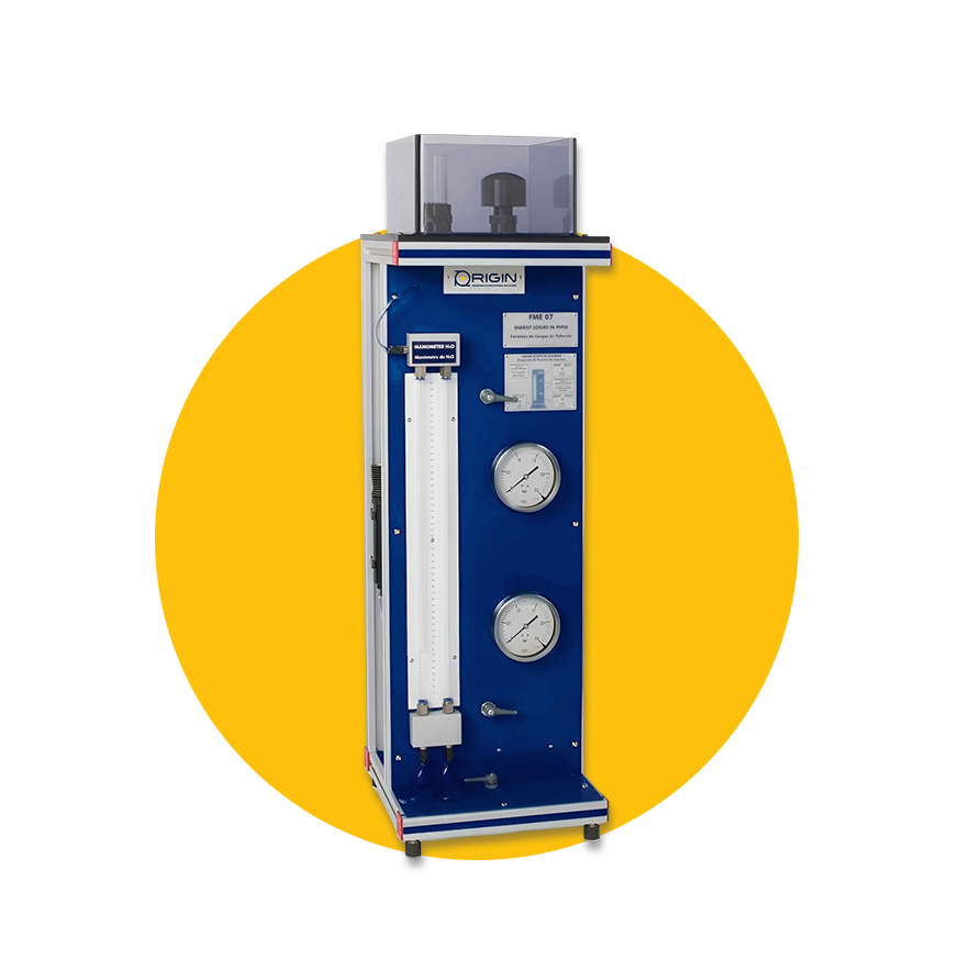
Energy losses in pipe
Code : (MF-35)
The apparatus is designed for examining and observing the pressure drops in pipe components. This experimental setup enables the examination of the impact of various pipe shapes on flow. Pipe with quick connector to be coupled to the water outlet’s
mouthpiece at the Hydraulics Bench (FME00) or the Basic Hydraulic Feed System
6 mm external/4 mm inner diameter metallic test pipe.
Water column differential manometer.
Constant height tank.
Two Bourdon type manometers.
• Research pressure drops and loss coefficients
• Calculate a pipe's characteristic
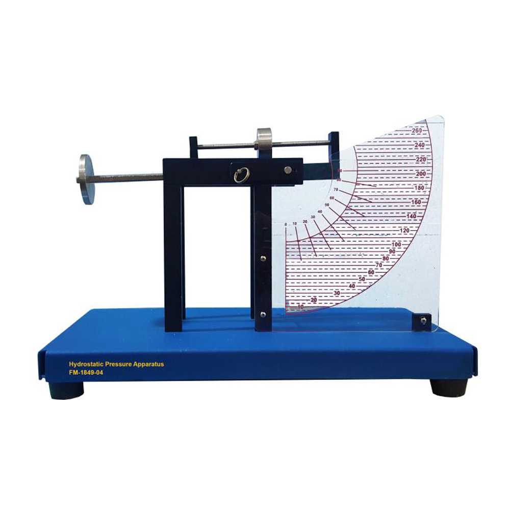
Hydrostatic pressure
Code : (MF-36)
The hydrostatic pressure apparatus is a tabletop kit created to determine forces on surfaces subjected to hydrostatic pressure. Hydrostatic pressure plays a crucial role in various engineering sectors, including shipbuilding, hydraulic engineering, and building services.
• Investigation of the way pressure spreads across a surface submerged in a stationary liquid
• Demonstration of sideways force caused by hydrostatic pressure
• finding the point where pressure force is concentrated and the geometric center
• calculating the total inward force caused by the pressure
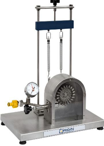
Main turbine unit
Code : (MF-37)
The educational unit serves as a supply unit for examining various turbines utilized in fluid mechanics, including a reaction turbine, Pelton turbine, and action turbine. It features a stainless steel tank and a submersible pump with adjustable speed.The trainer includes the following components: compressor, tubular combustion chamber and high-pressure turbine; fuel system; starter and ignition system; lubrication system; power turbine; generator; and measuring and control equipment.
• Conducting simple tests on a pump.
• Utilizing the reaction turbine, Pelton Turbine, and Action Turbine.
• Establishing standard turbine curves
• Creating performance curves with different turbine speeds
• Calculating efficiencies

Reynolds
Code : (MF-38)
The Reynolds numbers apparatus is a bench top kit designed to be connected to the hydraulic main unit, offering valuable hands-on experience for learners.
It demonstrates the importance of visualizing laminar and turbulent flows.
Additionally, the experimental method can be used to find the critical Reynolds number.
The experimental unit consists of a transparent pipe section through which water flows, with flow-optimized inlet. A valve can be used to adjust the flow rate in the pipe section. Ink is injected into the flowing water. A layer of glass beads in the water tank ensures an even and low-turbulence flow.
- The experimental unit consists of a transparent pipe section through which water flows, with flow-optimized inlet. A valve can be used to adjust the flow rate in the pipe section. Ink is injected into the flowing water. A layer of glass beads in the water tank ensures an even and low-turbulence flow.
• visualizing laminar flow
• illustrating the transition zone
• illustrating turbulent flow
• identifying the critical Reynolds number
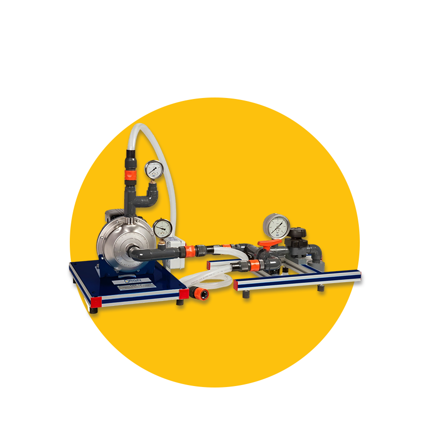
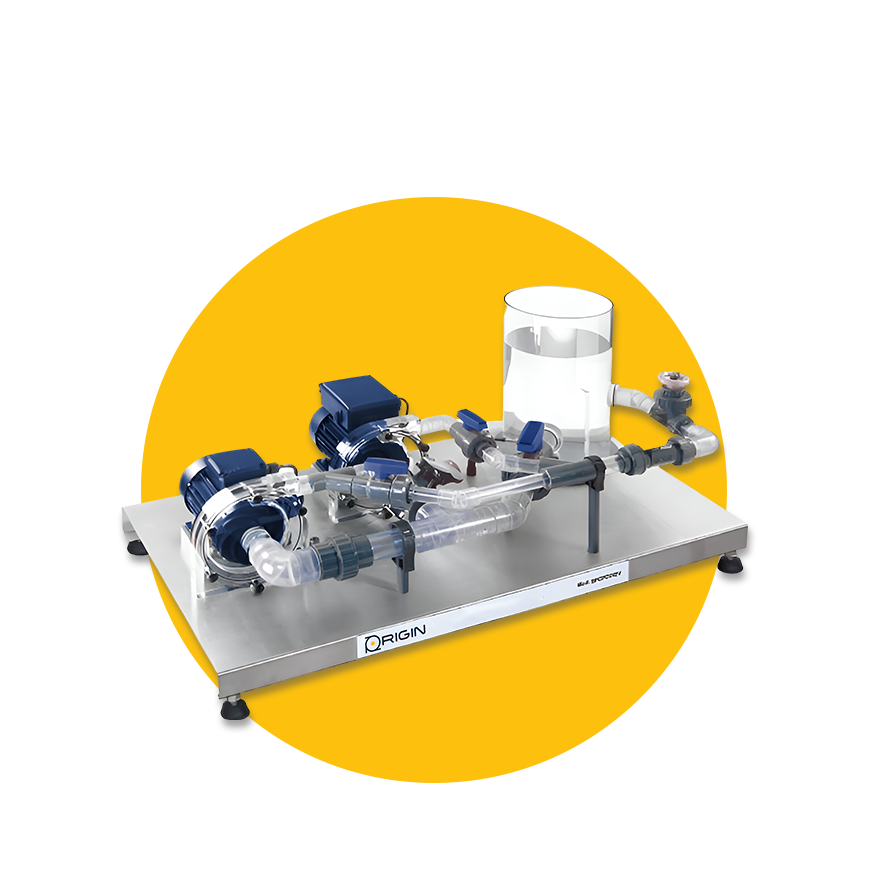
Centrifugal pumps
Code : (MF-39)
The trainer assembly is suitable for examining a centrifugal pump and for capturing a standard pump characteristic curve.
It demonstrates the importance of visualizing laminar and turbulent flows.
Additionally, the experimental method can be used to find the critical Reynolds number. The pump is installed in a pipes system which avoids the permanent water spending during the operation because it is a closed circuit.
The Centrifugal Pump Bench, allows the measurement of the most typical parameters of the centrifugal pump:
Speed motor.
Total impelled flow.
The admission and discharge pressure.
Torque.
• Getting to know how a centrifugal pump operates and its traits by conducting experiments.
• Documenting the pump's characteristic curve while maintaining a consistent pump speed.
• Taking note of the pump's traits at various speeds.
• Charting power and efficiency curves.
Series & parallel
Code : (MF-310)
The setup of pumps is designed to investigate how pumps are connected in series and parallel configurations.
The device can also be utilized to establish the pump performance curves.
• Studying the operation of pumps in series and parallel setups
• Calculating the total head
• Documenting the performance of the pumps
• Calculating the hydraulic power
• Finding the working point
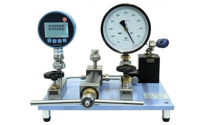
Calibration of pressure gauges
Code : (MF-311)
This educational unit is meant for bench top use and aims to introduce the fundamentals of manometer calibration. Additionally, it demonstrates how a Bourdon tube pressure gauge and a piston manometer operate.
• The operational mechanism of a Bourdon tube pressure gauge
• Adjusting manometers, recording the applied pressure
• Identifying consistent inaccuracies
• Principle of operation and function with a piston manometer
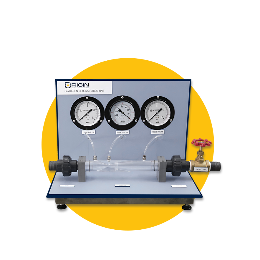
Cavitation
Code : (MF-312)
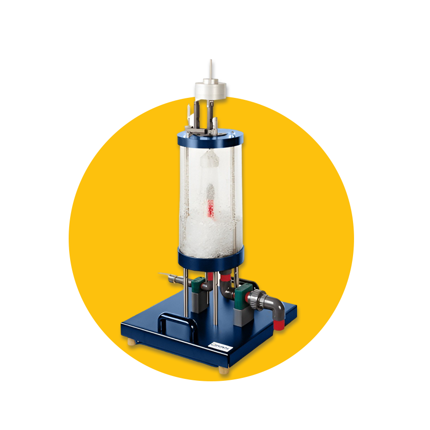
The trainer is appropriate for illustrating cavitation phenomena through the Venturi nozzle example. In the Venturi nozzle, pressure is transformed into kinetic energy and back again. Vapor bubbles develop in the narrowest part of the nozzle.
• The Venturi nozzle's purpose
• The relationship between pressure and flow rate
• Cavitation phenomena under varying flow rates and pressures
Flow visualization
Code : (MF-313)
The purpose of the Laminar Flow Streamlines Visualization Trainer is to show the flow patterns in ideal fluids. The instructor utilizes water as a running medium and ink as a contrasting medium to enhance visibility.
• influence of sources and sinks
• visualization of streamlines
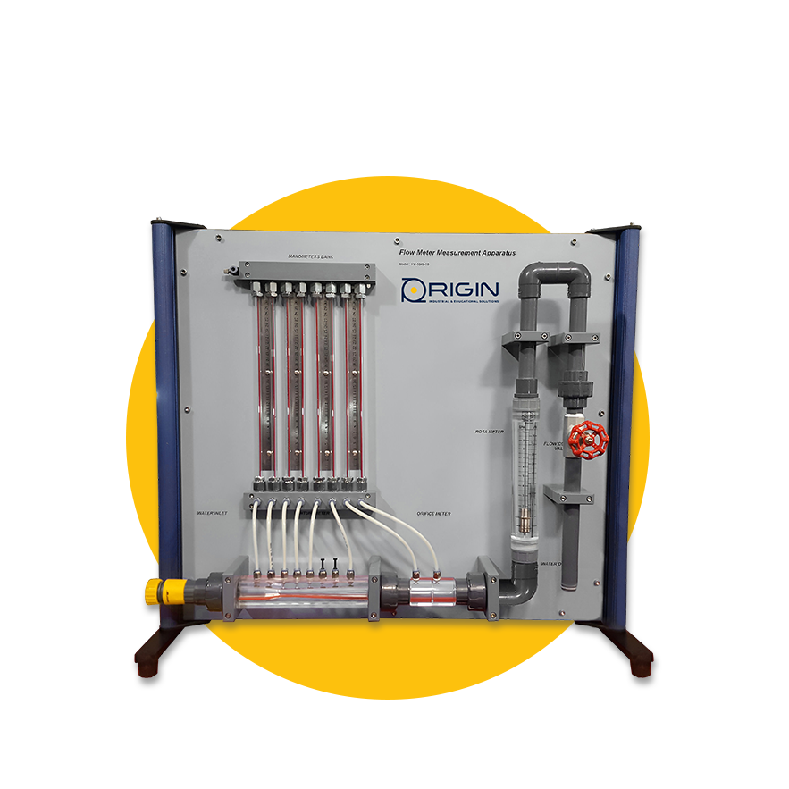
Methods of flow measurements
Code : (MF-314)
The experimental unit allows students to get to know different techniques for measuring flow in pipe systems and use them practically. Various measuring instruments are included in the experimental unit for determining the flow rate.
• Measuring pressure using a Pitot tube
• Evaluating various devices for measuring flow
• Calculating the respective flow coefficients
• Adjusting measurement instruments

Stability of floating bodies
Code : (MF-315)
The apparatus is capable of examining the stability of a floating object and graphically identifying the metacenter.
Furthermore, it allows for the determination of the buoyancy of the floating object. Setting up the experiment is straightforward and is well-suited for hands-on work in small groups.
• Investigation and perseverance in understanding Buoyancy
o The center of buoyancy,
o The center of gravity,
o The metacenter and stability while heeling.
